

PDF Download
 资料下载
资料下载
Product performance characteristics
★ Full self-test, strong shock resistance and stable performance
★ High resolution, which can protect fingers. Easy and diverse installation methods
★ Easy alignment of optical axis, strong resistance to light and electromagnetic interference
★ Low power consumption design, short response time, high reliability
Technical parameters
| Appearance size | 50mm*35mm |
| Detection distance | 0~5000mm (special length can be customized) |
| Number of optical axes | 4~160 (others can be customized) |
| Resolution | 10mm, 15mm, 25mm, 45mm |
| Optical axis spacing | 5mm, 10mm, 20mm, 40mm |
| Supply voltage | DC24V±20% |
| Power | <5W |
| Response time | <10ms |
| Output type | NPN/PNP |
| Output current | ≤200mA |
| Working environment humidity | -10~55℃ |
NPN wiring diagram
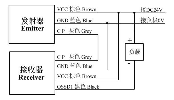
Working power supply: DC24V±20%.
Working status: When the light is on, both sides of the transmitter and receiver are green, and when the light is blocked, the receiver is red.
Output status: OSSD1 signal line outputs OV when the light is on, and the maximum drive current is less than or equal to 200mA. When the light is blocked, the OSSD1 signal line has no output and is floating.
Connection method:
1. Connect the brown wire VCC of the transmitter to the brown wire VCC of the receiver, and then connect the positive power supply DC24V.
2. Connect the blue line GND of the transmitter to the blue line GND of the receiver, and then connect the negative pole OV of the power supply.
3. The gray line CP of the transmitter is connected to the gray line CP of the receiver.
4. The transmitter black line OSSD1 is connected to the receiver black line OSSD1, which is the output signal line and connects to the PLC port Or connect the negative pole of the relay.
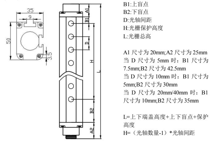
Dimensional drawing
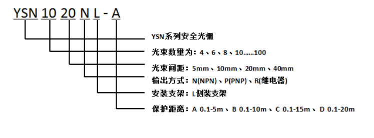
Model specification description
YSN series selection table
| Optical axis spacing (5mm) | |||
|---|---|---|---|
| Number of beams (n) | Protection height (mm) | Shell height (mm) | Specification model |
| 16 | 75 | 175 | YSN1605 |
| 24 | 115 | 210 | YSN2405 |
| 32 | 155 | 250 | YSN3205 |
| 40 | 195 | 290 | YSN4005 |
| 48 | 235 | 330 | YSN4805 |
| 56 | 275 | 370 | YSN5605 |
| 64 | 315 | 410 | YSN6405 |
| 72 | 355 | 450 | YSN7205 |
| 80 | 395 | 490 | YSN8005 |
| Optical axis spacing (10mm) | |||
|---|---|---|---|
| Number of beams (n) | Protection height (mm) | Shell height (mm) | Specification model |
| 8 | 70 | 150 | YSN0810 |
| 12 | 110 | 190 | YSN1210 |
| 16 | 150 | 230 | YSN1610 |
| 20 | 190 | 270 | YSN2010 |
| 24 | 230 | 310 | YSN2410 |
| 28 | 270 | 350 | YSN2810 |
| 32 | 310 | 390 | YSN3210 |
| 36 | 350 | 430 | YSN3610 |
| 40 | 390 | 470 | YSN4010 |
| Optical axis spacing (20mm) | |||
|---|---|---|---|
| Number of beams (n) | Protection height (mm) | Shell height (mm) | Specification model |
| 4 | 60 | 115 | YSN0420 |
| 6 | 100 | 190 | YSN0620 |
| 8 | 140 | 230 | YSN0820 |
| 10 | 180 | 270 | YSN1020 |
| 12 | 220 | 310 | YSN1220 |
| 14 | 260 | 345 | YSN1420 |
| 16 | 300 | 390 | YSN1620 |
| 18 | 340 | 430 | YSN1820 |
| 20 | 380 | 470 | YSN2040 |
| Optical axis spacing (40mm) | |||
|---|---|---|---|
| Number of beams (n) | Protection height (mm) | Shell height (mm) | Specification model |
| 4 | 120 | 210 | YSN0440 |
| 6 | 200 | 290 | YSN0640 |
| 8 | 280 | 370 | YSN0840 |
| 10 | 360 | 450 | YSN1040 |
| 12 | 440 | 530 | YSN1240 |
| 14 | 520 | 610 | YSN1440 |
| 16 | 600 | 690 | YSN1640 |
| 18 | 600 | 770 | YSN1840 |
| 20 | 760 | 850 | YSN2040 |
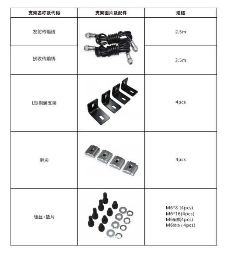
Accessory configuration
Precautions for installation and use:
(1) Preparation before installation
1. Before installation, please check the packing devices according to the packing list; when starting the installation, turn off the power of the machine tool to avoid danger;
2, prepare installation tools
◆Electric drill, drill bit (specification: Φ 3.2, Φ 5.0, Φ 6.8, Φ 10), tap (specification M4, M6, M8), cross head and slotted screwdriver, hexagonal wrench (specification: 4, 5, 6), live spanners, needle-nose pliers, etc.
◆The installation of the external controller fixing frame and the steel pipe support base requires a Φ6.8 drill bit and an M8 tap. The fixed installation of the built-in controller requires a Φ 3.2 drill bit and an M4 tap.
◆L-shaped bracket installation requires Φ 5.0 drill bit and M6 tap.
◆The cable routing hole needs a Φ10 drill bit.
(2) Calculation of safety distance
1. Calculation of safety distance
In order to ensure the personal safety of the operator, the installation location of the photoelectric protection device must meet the requirements of the safety distance. Otherwise, there is still the possibility of accidents.
◆Safety distance refers to the minimum distance between the light curtain of the photoelectric protection device and the cutting edge of the mold. The calculation method should be calculated according to the formula according to the braking method of the press, or determined by referring to the following table.
◆For the press that the slider can stop at any position of the stroke, the safety distance: Ds=1.6 (T1+T2)
Where: Ds-----safe distance, in meters (m); 1.6----hand extension speed, in meters/second (m/s); T1-----photoelectric protection device The response time of 0.02 second (s); T2-----the braking time of the press, that is, the time from the start of braking to the stop of the slider, in seconds (s), measured from the actual braking situation;
◆For the press where the slider cannot be stopped at any position of the stroke, the safety distance;
Ds=1.6Ts
where: Ds-----safety distance, unit (m); 1.6—hand extension speed, unit m/s (m/s); Ts—leave the light curtain from the hand (that is, the starting slider is allowed) The time until the press slider reaches the bottom dead center, that is, the down stroke time of the slider, in seconds (s). It can be calculated or actually measured according to the following formula
Ts=(1/2+1/N)Tn
In the formula: N-the number of engagement grooves of the clutch; Tn-the time of one revolution of the crankshaft, in seconds (s)
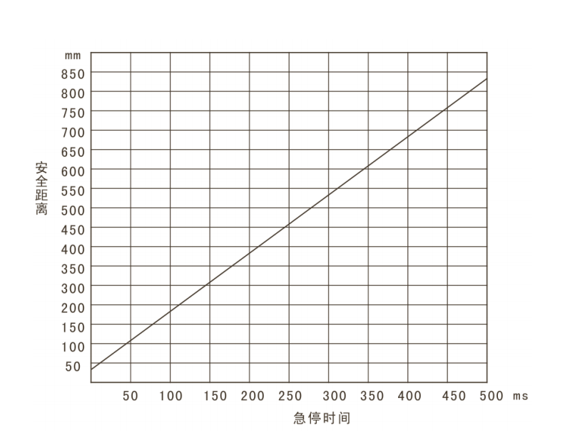
Safe distance is one of the necessary conditions to ensure that the photoelectric protection device realizes the protection function, and the safety distance must be ensured when installing! ! It is very wrong to protect the light curtain close to the dangerous area.
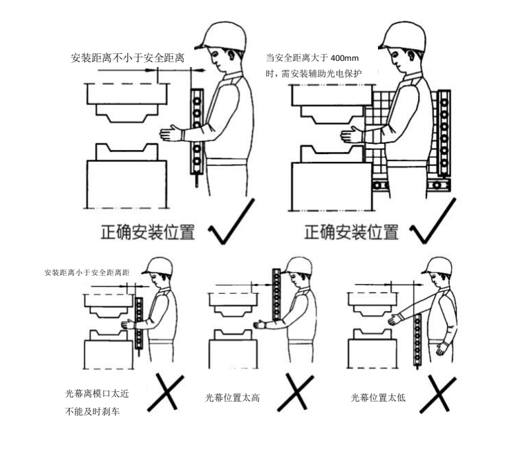
(3) Confirmation of installation location
The installation position refers to the position of the light curtain of the photoelectric protection device relative to the upper and lower die openings of the machine tool, that is, under the premise of ensuring a safe distance, the lowest light of the photoelectric protection device shall not be higher than the lower edge of the lower die opening. The top beam shall not be lower than the upper edge of the upper die opening. This involves the choice of the protection height of the photoelectric protection device.
+86 134-1679-4025 Mr. Yang